BSPD Brakelight Circuit

My first project for Olin Electric Motorsports was redesigning the mission-critical brake system plausibility device. The analog circuit controls one node of the shutdown circuit on the car, helping to ensure the safety of the driver and vehicle.
How to PCB
The final deliverable for this project was a PCB, or printed circuit board, which would slot into the car’s low voltage box. Along with performing a critical safety check for the electrical systems during racing, the circuit also handles activating the brakelight based on the reading of an brake pressure sensor. Understanding the project was the first–and one of the hardest–tasks I had to accomplish.
Brake System Plausibility
The brake system plausibility device (BSPD) is an analog circuit that provides a critical safety check for the car. It ensures that the motor controller isn’t supplying current to the motor while the brake is being pressed. This condition is dangerous because it means the driver has lost control of the car, and so it causes the car to shut down.
In ordinary conditions, the throttle circuit (which is responsible for making the car accelerate) should prevent this from happening, but in the event that that doesn’t happen, the BSPD circuit is a backup.
The circuit operates on a fairly simple AND gate to check for the condition, and implements a set-reset latch to ensure that the car cannot begin moving again until it is power-cycled1.
Brakelight
The other parts of the circuit are the brakelight circuit, which reads an analog signal from a brake pressure sensor and activates the brakelight if it is above a certain threshold, and triggers a low-side drive that turns on the brakelight.
Learning the Ropes
This was my first serious electrical engineering project. When I started, my only experience was my AP Physics course, and we didn’t do anything even close to this.
The first step in a project like this is understanding the target. This took me a long time because I had very little concept of how the car worked. Over time, I picked up bits and pieces and finally began to understand what this circuit needed to do. So the next step was creating a schematic.
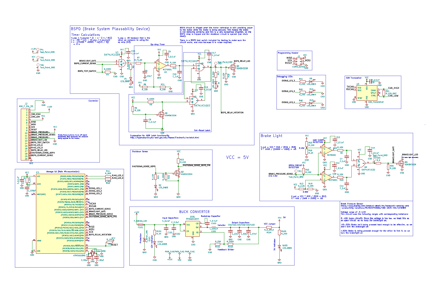
BSPD/Brakelight circuit schematic.
Schematics are the way electrical engineers detail the components that go on a board, like the resistors, integrated chips (microcontrollers), and LEDs. I broke up the schematic for this board into functional blocks: BSPD, brakelight, buck converter2, microcontroller, connector, and a few other bits and pieces.
After finishing a schematic and getting it reviewed, I began work on the layout. The layout is the design of the actual printed circuit board (PCB). It reads the schematic to figure out what components will go on the board, and then it is the responsibility of the designer to lay out the components and the wires between them such that everything is connected and works efficiently.
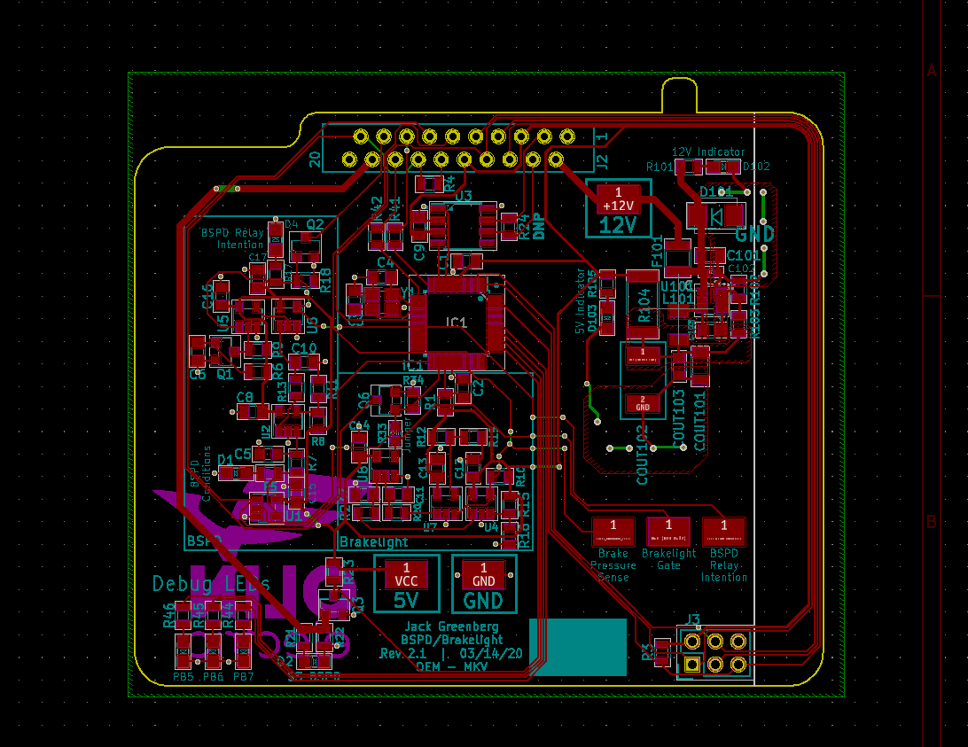
BSPD/Brakelight circuit layout.
Looking Back
This project was left in a strange state. I had just finished the layout and gotten it reviewed by the senior engineers on the FSAE team when all the students at Olin were ordered to vacate the campus due to concerns about COVID-19. I was able to ship one revision of the board and test it, and it worked as expected, but until we are back on campus and with the car, we won’t be able to ship the most recent version and test with the car.