I2C2

I wrote an implementation of the I2C protocol (inter-integrated chip) in C. It taught me a lot about writing and debugging embedded firmware.
I2C is a two-wire communication protocol, often used to foster communication between sensors and microcontrollers. I wrote the library for AVR chips, in particular the ATMega328p and ATMega16M1.
In a nutshell, the protocol works by using one wire as a clock signal (SCL) which then synchronizes the sender and receiver, and one wire as the data signal that transmits 8 bit messages with error handling.
Motivation
There were two motivations for the project:
- The electrical subteam for Olin Electric Motorsports, my school’s FSAE team, needed a microcontroller-agnostic I2C library to allow the ATMega16M1 (which has no I2C integration) to communicate with a sensor that outputs I2C, and
- I chose the previous reason as motivation for my Software Systems course project.
Additionally, I am very interested in the interface between hardware and software, and I wanted to teach myself more. Physical layer communication protocols like I2C, SPI, and CAN are very widely used and underlie a lot of the technology we use today, especially the internet.
Implementation
The library consisted of 3 files: i2c.c (the library), i2c.h (the header file), and a Makefile, as well as a testing file main.c. The header file contained constants for things like the microcontroller pins, clock speeds, and read/write mode indicators. The makefile included scripts for compiling and flashing the testing file on an Arduino as well as a script for generating a library file (i2c.a).
The main file of interest though is i2c.c, which contains the bulk of the code. The most difficult piece of the implementation was working on synchronization of the SCL and SDA lines. Because embedded C is so low level, it can be difficult to determine the state of a pin on a microcontroller1. So I developed a simple “stalling” method that would suspend the program until there was a change in one of the pins:
| |
This ended up being one of the most useful idioms in the library, because it allowed me to control when the SDA pin would change state, since according to the I2C spec it is only allowed to change when the SCL line is low.
Physical Setup
Because I2C uses open-drain/open-collector set up, it requires pull-up resistors on each line:
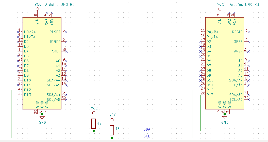
I2C schematic with pull-up resistors.
To develop the library, I used an Arduino, which uses an ATMega328p microcontroller, and an Analog Discovery, which is essentially a pocket-sized oscilloscope and signal interpreter. I learned about I2C using Texas Instruments’s I2C application report. I tested things like signal synchronization and clock frequency settings using the Analog Discovery’s oscilloscope, which generated results like this:
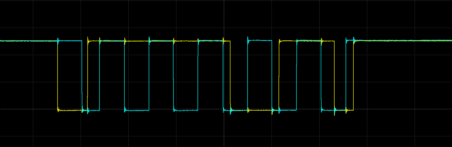
Oscilloscope reading of electrical signal: <START>11101<STOP>
Debugging
One of the hardest tasks in software, and in particular firmware, is debugging. Ordinarily, when I write Python or Go, there are semi-useful error messages that get printed out to a terminal with tracebacks that help you identify the origin of error. However, when you have no error messages, and instead are just looking at the readout of an oscilloscope, it can often be difficult to find your error source, especially while things are happening at high frequencies like 100kHz. So over time I developed debugging methods and strategies that would help me find sources of error.
My primary method was making single change to the code and looking for changes in the signal. These changes could be slight, like switching the order that two lines rise from a 0 state to a 1 state, or drastic, like the entire signal stuck in one, unchanging state. This debugging technique was especially useful when it came to synchronization issues, because it was sometimes difficult to tell whether or not I needed to stall while a line was high or a line was low.
For higher level issues, like figuring out–conceptually–how to enforce a start condition, it is also helpful to talk out loud to a friend.
Looking back
The project is not yet complete, and may remain on hold for a month or so. I nearly finished the primary->secondary2 communication channel, I just had issues pertaining to the inner mechanics of the ATMega328P pins.
I learned a lot about embedded systems from this project. I learned about timers on AVR chips and how different modes (i.e. PWM, CTC) can be useful in different settings. One of the most important lessons I learned was how to read a datasheet. Datasheets are long documents (on the order of hundreds of pages) that detail the usage, mechanics, and properties of electrical components. I spent a lot of time reading the ATMega328P datasheet.
Having started as a web developer, slowly making my way down the stack until I hit the physical layer has been an amazing and enlightening progression, and I feel that I have a firmer grasp on how the computer systems of the modern world work.
Looking forward
In the future I will be picking this project back up and finishing it. I need to work out the READ mode (for secondary->primary communication) and work on error handling with the read_ACK_NACK function.